- Die Antenne ist für den Sende-und Empfangsbetrieb im Grenz- Kurzwellenbereich (MF-HF 1.4-30 MHz) vorgesehen.
- In Verbindung mit einem Antennentuner ist die Antenne für Grenz- und Kurzwellengeräte sehr gut einsetzbar.
- Die Antenne ist für Mastmontage mit offener Einspeisung ausgelegt.
- Die Antenne hat eine sehr niedrige Eingangskapazität, um eine
bestmögliche Effizienz zu erreichen. Die Leistungsparameter der
Antenne sind abhängig von der Frequenz, es können aber
bedenkenlos 500 W Sender im gesamten MF-HF Band eingesetzt
werden. - Die Installation erfolgt einfach mit den beiden feuerverzinkten
Mastschellen. Die Antenne ist sehr leicht und hat eine minimale
Windfläche. Sie benötigt daher nur ein Mastrohr mit geringer
Stärke. - Die Glasfiberkonstruktion ergibt eine starre, autarke Bauweise mit
hervorragenden Schutzeigenschaften vor korrosiven maritimen
Einflüssen, z.B. UV-Strahlung, Salz, Abgase und Vereisung. - HF 7500-3 ist wartungsfrei und äusserst zuverlässig konstruiert.

Beschreibung
Spezifikationen
| Elektrisch DE | ||
|---|---|---|
|
||
|
||
|
||
|
||
|
||
|
||
|
||
|
||
| Mechanisch DE | ||
|---|---|---|
|
||
|
||
|
||
|
||
|
||
|
||
|
||
|
||
|
||
|
||
|
||
|
||
| Umwelt | ||
|---|---|---|
|
||
|
||
|
||
Diagramm und Montage
DETAILS ZUR MASTSCHELLE

DETAILS ZUR MASTSCHELLE

Bestellbezeichnungen
| Modell | Produkt Nr. | ||
|---|---|---|---|
| HF 7500-3 | 110000179 | Verfügbarkeit |
Installation and Application
The HF 7500-3 is a vertical multi-frequency whip antenna intended for operation in the HF frequency range 1.4 to 30 MHz.
In order to operate throughout the whole 1.4 to 30 MHz frequency range, the HF 7500-3 must be combined with a suitable Antenna Tuning Unit (ATU), which must be properly matched to the transmitter unit used.
Most companies which sell HF radio equipment, also sell matching ATU units for the particular radio equipment.By the length of 7.5 m, the HF 7500-3 functions optimally in the 1.4-30 MHz frequency range with most ATU units.
Antenna height
In the HF frequency range 1.4 to 30 MHz, antenna height is not important, because communication typically takes place by ionospheric radio wave propagation, contrary to the VHF and UHF frequency bands, where ground wave propagation with line-of-sight conditions is the normal communication way, and antenna height therefore is of high importance.
Therefore, a HF vertical whip antenna typically is mounted either direct on the earth surface, or at quite low height.
Land installations
In land installations, we recommend the vertical HF 7500-3 antenna to be mounted on a short ø45 - 65 mm mast tube which either is driven 6-8 feet in the ground or cast into the ground, to be able to cope with the occurring antenna wind load at the particular location.The free height of the mast tube shall be a few feet above the ground.
The antenna must be placed in an open area free of nearby obstructions like buildings, trees etc. and where sufficient space is present to establish an effective RF ground radial system.
RF ground system
In order to ensure high efficiency of the antenna system, the antenna and ATU shall be provided with a low-loss RF ground system as counterpoise / return path for the antenna RF current.
The mast tube itself is not suitable as RF ground system, as due to conductivity of the ground, RF currents only flow within a few inches of the surface. Therefore, nearly no RF current will flow in most of the mast tube and it will therefore have no or little effect as counterpoise for the antenna. This is especially valid in coastal areas with sandy soils.
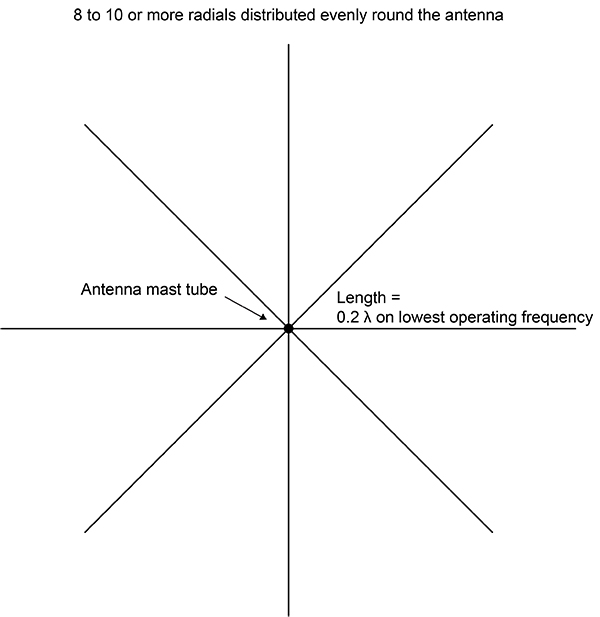
Therefore a radial system must be established with min. 4, but preferably 8 - 10 or more medium gauge copper wires with a length of ideally 0.2 wavelength at the lowest operating frequency, which fans out circular round the antenna.
The radials shall be placed on the surface of the ground, or buried just below the surface, in depth not more than an inch or so.
The radials are connected to an angled metal radial plate, which is clamped to the mast tube just above the ground surface.
ATU
The ATU shall be mounted on the mast tube with the antenna terminal upwards, just below the bottom end of the antenna whip.
The HF 7500-3 antenna feeder connection and the ATU antenna terminal are connected as direct as possible with a short open feeder wire, which in fact is a single piece of medium-gauge copper wire, self-supported or supported by some porcelain insulators. As high voltage can occur on the feeder wire, it must be mounted with a distance of min. 30 mm to the mast tube or other metal objects.
The ATU ground terminal is connected to the metal radial plate by heavy gauge wire or a metal strap. Generally, for details in the installation procedure, please refer to the ATU instruction manual, where installation examples often are described. This installation is valid for both coastal areas and built-up areas.
Vessel installations
The HF 7500-3 is only suitable for use on metal vessels.
In vessel installations, the vertical HF 7500-3 antenna must be mounted on a short suitable mast tube, which is connected to the vessel’s ground. The ATU shall be mounted either on the mast just below the bottom end of the antenna whip or somewhere on the vessel deck as close as possible to the antenna mast. The HF 7500-3 antenna feeder connection and the ATU antenna terminal are connected with a short open feeder wire. The ATU ground terminal shall be connected to the vessel’s ground by a short heavy gauge wire or a metal strap.
Generally, for details in the installation procedure, please refer to the ATU instruction manual, where installation examples often are described.
Typical land Installation

Suitable RF Ground System (top view)
Weitere Produkte

Halterungen
Amphenol Procom design a wide and varied range of Wall Brackets and Antenna Mounting Poles. Robust professional install and longevity. See our collection here.

Welliges Kabel
Amphenol Procom offers several Corrugated Cables like Super Flexible- and Cobber Cables. All are of the highest quality on the market. See our collection.

Zubehör
Amphenol Procom offer a wide range of Mobile Antenna Components, which incl. Connectors, Reinstallation Kits, Miniature Junction Box etc. Read more.
