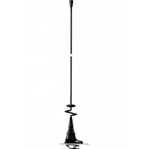
- Mobile mount with a nice, “streamline”-look, which can be installed everywhere on the car in an 19 mm dia. hole.
- Especially suited for mounting on the narrow strip on rear wing between trunk lid and car side.
- M6 thread whip-mounting system.
- Very low requirements to installation depth both under and after installation.
- Designed for installation with access from the outside only.
- Bendable section in mount makes whip tiltable 30° by hand.
- Complete line of whips available for all communications bands up to 1300 MHz.
- Mounting body made of stainless steel !
- Choice between two connection principles:
- XG-Combi mount: FME-connection and GPS (supplied without cable).
- XGP4-Combi mount: Permanently attached 4 m RG 58 cable terminated with FME-connector and GPS.
- GPS-antenna for fixed installations.
- Full hemispherical coverage.
- Built-in high-gain, low-noise amplifier.
- Right-Hand Circular Polarization (RHCP).
- 2.85 V - 5 V supply voltage (typical 3 V).
- ECE R118.02 approved cable.

Supports mobilesXG-Combi Mount
GPS mount for GPS Antennas and Other Frequencies
Description
Spécifications
| Électrique FR | ||
|---|---|---|
|
||
|
||
| Mécanique FR | ||
|---|---|---|
|
||
|
||
|
||
|
||
|
||
|
||
|
||
|
||
|
||
|
||
|
||
| Antenne GPS | ||
|---|---|---|
|
||
|
||
|
||
|
||
|
||
|
||
Désignations de commande
| Model | N ° de produit | Description | |
|---|---|---|---|
| XG-COMBI MOUNT | 130002032 | XG-Combi mount with FME-system | |
| XGP4-COMBI MOUNT | 130002043 | XGP4-Combi mount with 4 m RG 58 cable and FME-connector | |
| Accessories FME-Cables | |||
| 1 m FME(f) to FME(f) | 130000437 | ||
| 2 m FME(f) to FME(f) | 130000447 | ||
| 3 m FME(f) to FME(f) | 130000457 | ||
| 4 m FME(f) to FME(f) | 130000466 | ||
| 5 m FME(f) to FME(f) | 130000474 | ||
| 6 m FME(f) to FME(f) | 130000483 | ||
| 4 m FME(f) to FME(f), white | 110000064 | ||
| 6 m FME(f) to FME(f), white | 110000066 | ||
| 12 m FME(f) to FME(f), white | 110000068 | ||
| 18 m FME(f) to FME(f), white | 110000069 | ||
| Accessories FME-Connectors | |||
| FME(f)-FME(f) | 130000583 | ||
| FME(m)-P(m) (Prolongation) | 130000565 | ||
| FME(m)-N(m) | 130000571 | ||
| FME(m)-SMA(f) | 130000578 | ||
| FME(m)-BNC(m) | 130000566 | ||
| FME(m)-TNC(m) | 130000569 | ||
| FME(m)-UHF(m) | 130000572 | ||
| FME(m)-MiniUHF(m) | 130000573 | ||
| FME(m)-MiniUHF(m)(Elbow) | 130000582 | ||
| FME(m)-BNC(m)(Elbow) | 130000580 | ||
| FME(m)-TNC(m)(Elbow) | 130000581 | ||
| FME(m)-SMA(m) | 130000577 | ||
FME-System Accessories - Note
For further information about other types of FME-cables and FME-connectors, please compare the cable and connector data sheets under accessories.
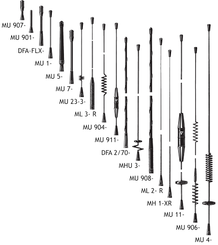
A Selection of the various whips which can be connected to the XG-Combi Mount
Installation
XG-Combi mount antenna types can be mounted anywhere on the car, however, roof top mounting is always recommended.
The oblong XG-Combi mount is able to be mounted on the often very narrow strip on the rear wing between the trunk lid and the side of the car.
Mounting can take place with access from the outside or inside when drilling an 19 mm dia. hole.
A good contact surface on the inside of the car body must always be ensured, thus enabling the base plate to get in direct contact with the metal parts of the car, which is of utmost importance for proper performance of the antenna.
When cleaning the car in car-washing machines, the whip is easily removed using a fork spanner, size 9 mm. The whip is refitted again by screwing it onto the thread stud and tightening it lightly with the spanner.
As the XG-Combi mount is internally equipped with a bendable section, the antennas can always be adjusted to an upright position independent of the tilt angle of the installation spot (up to 30° tilt).
1. Installation Dimension

2. Installation Steps

Do not use sealer on rubber gasket or other places.
Assembly Instructions
- Put GPS-FME-connector-cable through the gasket (2).
- Put the gasket (2) + GPS-part (1) over the body (B).
- Put the body (B) + gasket (3) + GPS-part (1) through the ø19 mm hole.
- Put the housing (4) over the body (B) and be sure that the GPS-part (1) fits into the square hole in the body (B).
- Put the threaded part over the body (B) and tighten max. 4 ±1 Nm!
- Put the corrugated plastic unit (6) over the body (B).
- Mount the antenna whip se figure 4.

EU and UK Declaration of Conformity
Hereby Amphenol Procom declare that the product type XG-COMBI MOUNT is in compliance with EU Directive 2014/53/EU and
the UK Radio Equipment Regulations 2017 (S.I. 2017 No. 1206).
The full text of the Declaration of Conformity is available at:
Produits associés

Antennes de combinaison GPS
Amphenol Procom have a huge assortment of GPS Antennas. Beneficial products for navigation/location applications. Read more here.

Profil bas / Covert
In our collection of Low Profile Antennas covering VHF and UHF bands with omnidirectional coverage. Best quality products on the market. View our collection.
Fouet Antennes
Amphenol Procom offers a comprehensive collection of quality Whip Antennas for nondirectional communication. See our product line here.
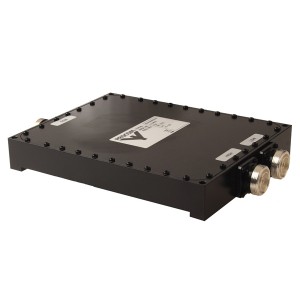
Diplexeurs
All Amphenol Procom Diplex filters are thoroughly tested, tuned and will be delivered prepared for installation. Custom-made is possible. Learn more.