- Active wideband receiver multicoupler for the VHF band and the low part of the UHF band with one input and two or four outputs.
- For use where a number of receivers have to share the same antenna.
- Wide frequency range. Covers 30 - 960 MHz.
- Other versions available:
- High-dynamic range amplifier built in to compensate for loss in the multicoupler network.
- High OIP2 and OIP3.
- Low amplifier noise figure.
- High isolation between receiver outputs.
- 12 V operating voltage (24 V as option).
- DC supply on solder terminal or on 2.5 mm barrel DC connector.
- Coated with black vinyl to prevent corrosion.
- Available with N, TNC or BNC connector types.

Receiver MulticouplersHPRS
Miniature Receiver Multicoupler series for the VHF and low UHF band 30 - 960 MHz
Description
Specifications
| Electrical | ||
|---|---|---|
|
||
|
||
|
||
|
||
|
||
|
||
|
||
|
||
|
||
|
||
|
||
|
||
|
||
|
||
| Mechanical | ||
|---|---|---|
|
||
|
||
|
||
|
||
| Environmental | ||
|---|---|---|
|
||
|
||
Ordering Designations
| Model | Product No. | Description | |
|---|---|---|---|
| HPRS2-N(f) | 210000201 | OUTPUTS: 2 | |
| HPRS2-TNC(f) | 210001958 | OUTPUTS: 2 | |
| HPRS2-BNC(f) | 210000319 | OUTPUTS: 2 | |
| HPRS4-N(f) | 210000188 | OUTPUTS: 4 | |
| HPRS4-TNC(f) | 210001959 | OUTPUTS: 4 | |
| HPRS4-BNC(f) | 210000321 | OUTPUTS: 4 | |
| Accessories | |||
| Power Supply AC/DC 12V/1A EU/UK/US | 240000060 | ||
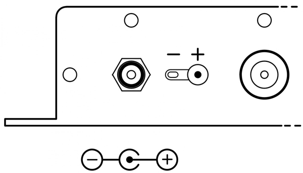
DC Power Supply connection
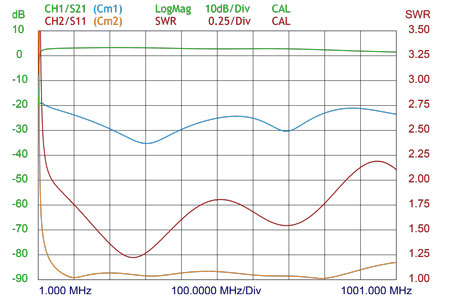
Typical Gain and VSWR Curve
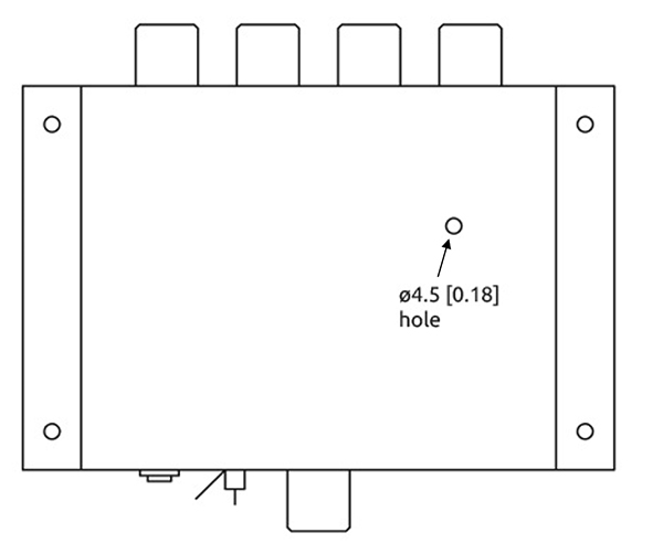
Mounting Details

All dimensions are given in mm [in.]
Gain adjustment HPRS
The HPRS is provided with gain adjustment option.
Gain is adjusted by turning a gain adjustment screw located 17 mm behind a ø4.5 mm hole on the top of the HPRS housing. See drawing below.
Access to the adjustment screw hole is made by removing the black label on the side of the box.
The adjustment screw is a slotted type, which can be adjusted by an ordinary 2 mm screwdriver.
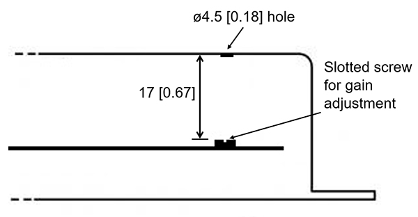
All dimensions are given in mm [in.]
EU and UK Declaration of Conformity
Hereby Amphenol Procom declare that the product type HPRS is in compliance with EU Directive 2014/53/EU and
the UK Radio Equipment Regulations 2017 (S.I. 2017 No. 1206).
The full text of the Declaration of Conformity is available at:
https://amphenolprocom.com/images/shop/catalog/pdf-for-catalouges/Declaration-of-Conformity-HPRS.pdf
Power Supply AC/DC 12V/1A EU/UK/US

Related products

Cavity Combiners
RF Cavity Combiners by Amphenol Procom for Tx 150-300 W radio systems in 60-500 MHz. Standard products are 2 to 8 channels. Read more here.

Combiner Components
Amphenol Procom offers a wide range of specific RF components to be implemented in combiner systems or as stand-alone radio parts. See various options here.


Hybrid Combiners
Hybrid Combiners by Amphenol Procom for Tx 35-100 W in frequency range 60-1000 MHz. Standard products are 2 to 8 channels. Learn more.