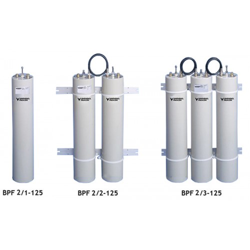
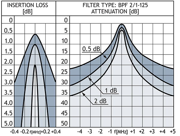
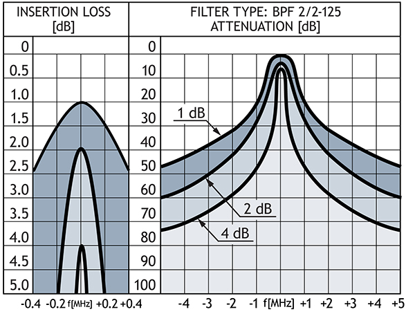
- High power base station band-pass filters for the 140 - 175 MHz range.
- The use of large ø125 mm cavities means a high Q,
resulting in a very narrow passband. - The large dimensions also mean a high power rating.
- Unloaded Q of a single cavity is approx. 4500.
- High frequency stability on temperature and power.
- Mounted on 19” brackets.**
Band Pass FiltersBPF 2/...-125
Band-Pass Filters for the 150 MHz Band
Description
Specifications
| Electrical | ||||
|---|---|---|---|---|
|
||||
|
||||
|
||||
|
||||
|
||||
|
||||
|
||||
| Mechanical | ||||
|---|---|---|---|---|
|
||||
|
||||
|
||||
|
||||
| Environmental | |||
|---|---|---|---|
|
|||
|
|||
Ordering Designations
| Model | Product No. | |
|---|---|---|
| BPF 2/1-125 | 200000956 | |
| BPF 2/2-125 | 200000986 | |
| BPF 2/3-125 | 200000961 |


