- Diplexer for combining or splitting the two ranges 0 – 400 MHz and 440 – 520 MHz.
- Eliptical filter design ensures high isolation across the entire pass ranges.
- High power handling capability.
- Low insertion loss.
- Low weight.
- Wide temperature range.
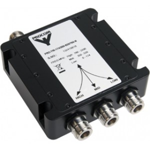
- Milled aluminium box ensures extraordinarily high mechanical strength.
- Black vinyl-coated to prevent corrosion.
- N-connectors on all ports (standard).
- Also available with SMA-, TNC- or BNC- connector types.
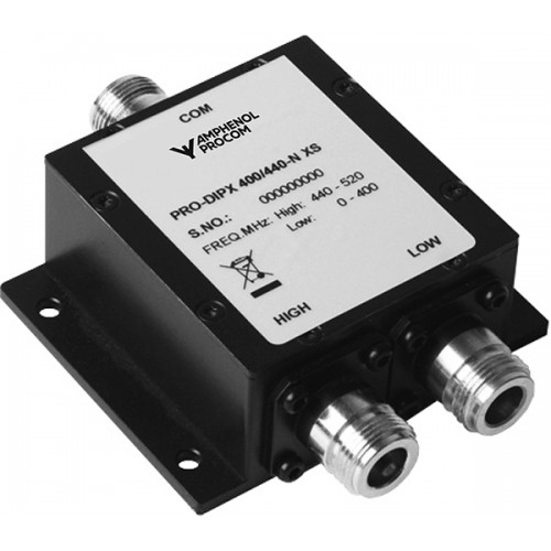
Diplex FiltersPRO-DIPX 400/440-... XS
50 W Diplexer for the 0 - 400 MHz and 440 - 520 MHz Ranges
Description
Specifications
| Electrical | ||
|---|---|---|
|
||
|
||
|
||
|
||
|
||
|
||
|
||
| Mechanical | ||
|---|---|---|
|
||
|
||
|
||
|
||
| Environmental | ||
|---|---|---|
|
||
|
||
Ordering Designations
| Model | Product No. | |
|---|---|---|
| PRO-DIPX 400/440-N XS | 200002525 | |
| PRO-DIPX 400/440-SMA XS | 200002534 | |
| PRO-DIPX 400/440-TNC XS | 200002535 | |
| PRO-DIPX 400/440-BNC XS | 200002536 |
Installation
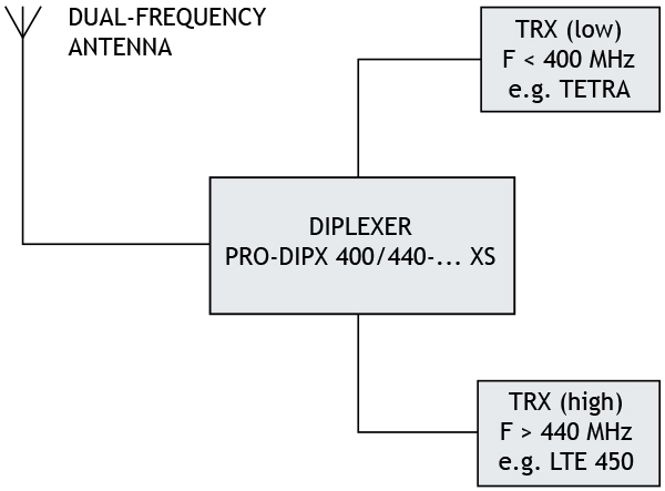
The PRO-DIPX 400/440-... makes it possible to use only one antenna for the operation of two transceivers (one in each range). See the figure. The antenna must be a dual-frequency antenna, i.e. it must be resonant on the actual frequencies in the two bands.
The transceivers may be used independently and will have no degrading influence on each other. Typically, the diplexer is installed next to the transceivers and only one cable is used between the diplexer and the antenna. The diplexer is suitable both for base station and mobile use.
The main tasks of the diplexer are to protect the individual receiver input from being destroyed by the transceiver in the contrary band and to ensure a low-loss path between the transceiver and the antenna which is not loaded by the other branch.
The diplexer can be operated together with any set of transceivers operating within the 0 - 400 MHz and 440 - 520 MHz frequency bands.
Dual-frequency antennas are available for both mobile and base station applications.
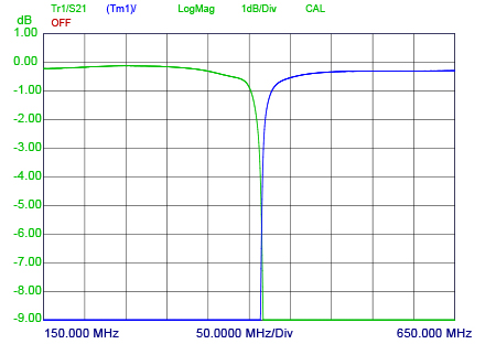
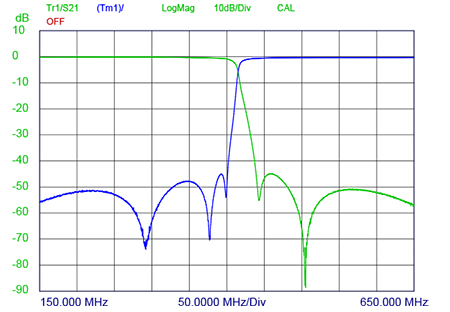
Typical Response curves
Insertion Loss [dB]
Port Attenuation [dB]
Mountion Details
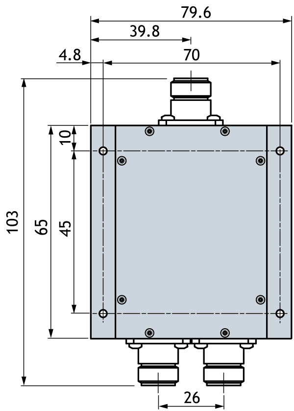
All dimensions are given in mm.
Note
* Temperature on box surface. Adequate cooling to keep max. temperature below +60 °C must be provided.
Related products

Power Splitters and Dividers
Power Dividers and Splitters in 2-4-way configurations. Max. power up to 500 W in frequency range 70-2700 MHz. Read more.

Mounting Kits for Filters
Amphenol Procom provides Mounting Kits for a wide range of Multiplexers and Duplex Filters with repeater. Learn more of our product line here.
Multiplexers
RF Multiplex Filters portfolio by Amphenol Procom consist of quality Triplex Filters and Quadroplex Filters with high performance. Learn more here.
