- High power base station band-pass filters for the 380 - 470 MHz range.
- The use of large ø125 mm cavities means a high Q, resulting in a very narrow passband.
- The large dimensions also mean a high power rating.
- Unloaded Q of a single cavity is approx. 4500.
- High frequency stability on temperature and power.
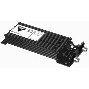
- 19” mounting brackets are available as an option.
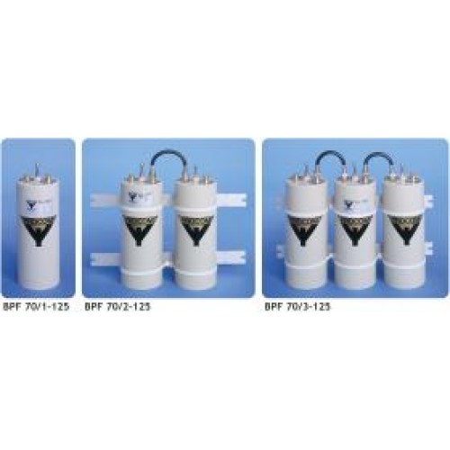
Band Pass FiltersBPF 70/...-125
Band-Pass Filters for the 450 MHz Band
Description
Specifications
| Electrical | ||||
|---|---|---|---|---|
|
||||
|
||||
|
||||
|
||||
|
||||
|
||||
|
||||
| Mechanical | ||||
|---|---|---|---|---|
|
||||
|
||||
|
||||
| Environmental | ||||
|---|---|---|---|---|
|
||||
|
||||
Diagram and Mounting
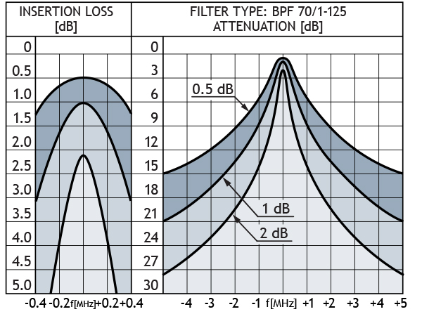
TYPICAL RESPONSE CURVES

Ordering Designations
| Model | Product No. | |
|---|---|---|
| BPF 70/1-125 | 200000962 | |
| BPF 70/2-125 | 200001049 | |
| BPF 70/3-125 | 200001050 |
Typical response curves
Typical response curves
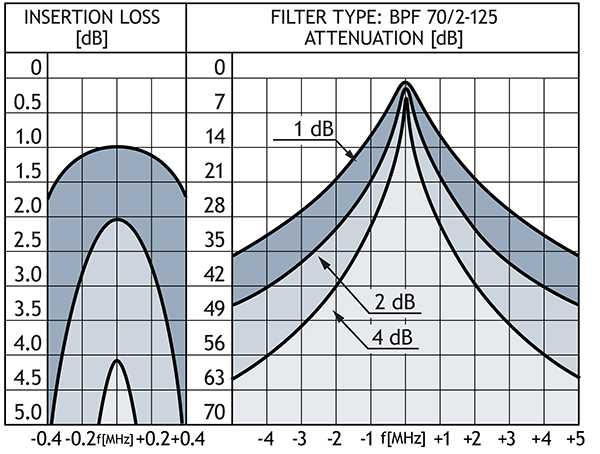
Diagram 2
Typical response curves
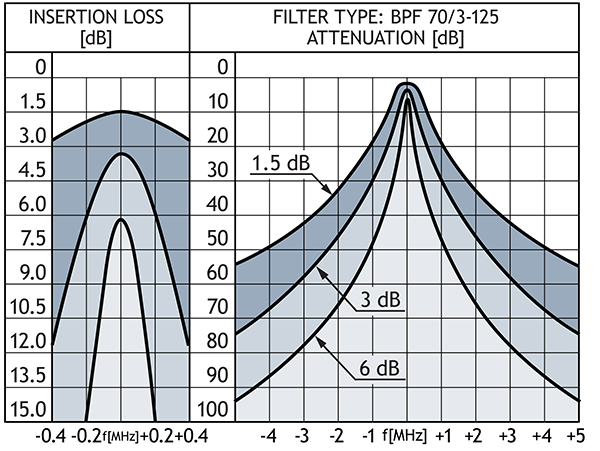
Diagram 3
Related products
Band Reject Filters
Amphenol Procom’s portfolio of HF, VHF and UHF Band reject Filters works with input power up to 350 W and are customizable. Read more.

High Pass Filters
High Pass Filters by Amphenol Procom are highly used for protection of PMR, DMR and LMR radio against high power television or FM broadcast radio systems.

Low Pass Filters
In Amphenol Procoms Low Pass Filters the spectrum of pass band are from 0-2100 MHz and stop band from 138 MHz to 12.4 GHz. View our products line here.

Mounting Kits for Filters
Amphenol Procom provides Mounting Kits for a wide range of Multiplexers and Duplex Filters with repeater. Learn more of our product line here.