- Field-tunable dual-frequency antenna which makes it possible to:
- operate 160 and 450 MHz transceivers alternately on the same antenna
- operate two transceivers (160 and 450 MHz) at the same time on one antenna using a diplexer (type DIPX 225/330 – must be ordered separately). - Only a single hole has to be drilled instead of two.
- Car appearance is not destroyed by an “antenna farm”.
- Ideal for covert services.
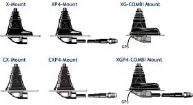
- Stainless steel X-mount with M6-thread whip-fastening system.
- Simple mounting exclusively with access from the outside.
- Choice between two connection principles:
- X-mount, CX-mount: FME-connection (supplied without cable).
- XP4-mount, CXP4-mount: Permanently attached 4 m cable terminated with FME-connector.
- XG-Combi mount: FME-connection and GPS (supplied without cable).
- XGP4-Combi mount: Permanently attached 4 m cable terminated with FME-connector for whip and 0.15 m RG 178 with MFME for GPS.
- Easily removable whip for car wash.
- GPS-antenna for fixed installations.
- Full hemispherical coverage.
- Built-in high-gain, low-noise amplifier.
- Right-Hand Circular Polarization (RHCP).
- 2.85 V - 5 V supply voltage (typical 3 V).

Whip AntennasMHU 3-X, MHU 3-CX, MHU 3-XG
Dual-frequency Mobile Antenna for the 160 and 450 MHz Bands
Description
Specifications
| Electrical | ||
|---|---|---|
|
||
|
||
|
||
|
||
|
||
|
||
|
||
|
||
|
||
| Mechanical | ||
|---|---|---|
|
||
|
||
|
||
|
||
|
||
Ordering Designations
| Model | Product No. | Description | |
|---|---|---|---|
| MHU 3-X | 130000770 | X-mount (oblong) with FME-system | |
| MHU 3-CX | 130000771 | CX-mount (circular) with FME-system | |
| MHU 3-XG | Contact for availability | XG-combi mount (oblong) with FME-system and GPS | |
| MHU 3-XP4 | 130000776 | XP4-mount (oblong) with 4 m cable and FME-connector | |
| MHU 3-CXP4 | 130000772 | CXP4-mount (circular) with 4 m cable and FME-connector | |
| MHU 3-XGP4 | 132000412 | XGP4-combi mount (oblong) with 4 m cable, FME-connector and GPS |
The whip is compatible with all below mounts
Connection Diagram
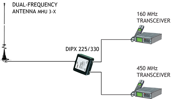
Operation using a diplexer
In case of operating two transceivers on one antenna at the same time, a diplexer, type DIPX 225/330 is necessary to complete the system. The tasks of the diplexer are to protect the two receiver inputs from being destroyed by the transmitter in the contrary band, and to ensure a low-loss path between the transceiver and the antenna, which is not loaded by the other branch. For further details please see the separate data sheet on the DIPX 225/330. The diplexer fully covers both bands and, consequently, tuning to specific frequencies is not required.
Please Note
With this type of combination antenna only certain frequenciesfrom the segments 140 - 170 MHz and 400 - 480 MHz can be covered at the same time. The combination area corresponding to “allowable” frequency pairs is shown in the diagram below. However, taking into account the inherent bandwidth of the antenna the combination area may be increased significantly. The antenna can also be delivered factory tuned. Please consult our price list concerning additional charges for adjustment by cutting.

Installation
Please refer to the data sheet of each individual mount to find the installation and assembly instructions.
Tuning Information
The MHU 3-X cannot be tuned to any pair of frequencies in the two bands. Further, the antenna must be equipped with a different kind of adjustment disc depending on the frequency pair in question. The antenna can be used without adjustmentdisc, with a small adjustment disc or with a large adjustment disc. All adjustment disc types are supplied with the antenna.
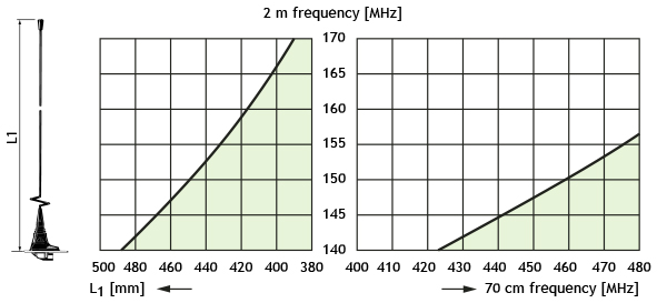
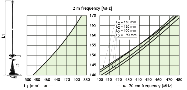
Use the diagrams below as follows:
1. Draw a horizontal line through the point on the vertical axis which corresponds to the 160 MHz frequency in question.
2. The drawn horizontal line intersects the shaded area over a certain band of
450 MHz frequencies. If the 450 MHz frequency to be covered is not included in the shaded area, try another diagram (another adjustment disc type). If the 450 MHz frequency is not covered in any of the diagrams, coverage of the frequency pair in question is not possible using this type of antenna. Please note, however, that taking into account the inherent bandwidth of the antenna (± 2 MHz in the 160MHz band and ± 12 MHz in the 450 MHz band) the combination area may be increased considerably.
For the relevant diagram:
3. Read the total length L1 on the left horizontal axis and cut the whip to this length.
4. Locate the 450 MHz frequency in question on the right horizontal axis and read the corresponding length L2 from the curves in the shaded area.
With No Adjustment Disc
With the Small Adjustment Disc
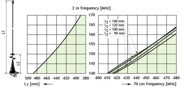
With the Large Adjustment Disc
Use an VSWR-meter to fine-tune the settings
Related products

Compact Combiners
View all Amphenol Procom hybrid Tx/Rx Compact combiners for VHF & UHF. To be used e.g. in mobile TETRA/PMR/LMR control stations. Learn more.

GPS Combination Antennas
Amphenol Procom have a huge assortment of GPS Antennas. Beneficial products for navigation/location applications. Read more here.

Low Profile Antennas
In our collection of Low Profile Antennas covering VHF and UHF bands with omnidirectional coverage. Best quality products on the market. View our collection.
Multiplexers
RF Multiplex Filters portfolio by Amphenol Procom consist of quality Triplex Filters and Quadroplex Filters with high performance. Learn more here.