- This antenna is intended for transmitting and receiving in the
MF-HF range 2 - 30 MHz. - Combined with an automatic antenna tuning unit (ATU) the HF 5000 forms a suitable antenna system for e.g. marine MF/HF SSB radio use.
- The antenna is designed for mast mounting with an open feeder installation.
- The antenna has very low base capacitance for best efficiency. The power rating of the antenna depends on frequency, but it can very safely be used with up to 500 W transmit power (dependent on max. power for the ATU) over the whole MF-HF band.
- Installation is easily carried out by means of the two hot galvanized mast clamps. The antenna has very small weight and minimum wind surface, thereby requiring only a minimum of mast strength.
- The glass fibre construction gives a stiff and self-supporting structure with extremely good resistance against the corrosive marine environment with UV-radiation, salt, exhaust gases and ice formation as the primary factors.
- HF 5000 is a maintenance-free and very reliable construction.

Description
Specifications
| Electrical | ||
|---|---|---|
|
||
|
||
|
||
|
||
|
||
|
||
|
||
|
||
| Mechanical | ||
|---|---|---|
|
||
|
||
|
||
|
||
|
||
|
||
|
||
|
||
|
||
|
||
|
||
|
||
| Environmental | ||
|---|---|---|
|
||
|
||
Diagram and Mounting
CLAMP DETAILS

Ordering Designations
| Model | Product No. | |
|---|---|---|
| HF 5000 | 110000109 |
Installation and Application
The HF 5000 is a vertical multi-frequency whip antenna intended for operation in the HF frequency range 2 to 30 MHz.
In order to operate throughout the whole 2 to 30 MHz frequency range, the HF 5000 must be combined with a suitable Antenna Tuning Unit (ATU), which must be properly matched to the transmitter unit used.
Most companies which sell HF radio equipment, also sell matching ATU units for the particular radio equipment.By the length of 5 m, the HF 5000 functions optimally in the
2 - 30 MHz frequency range with most ATU units.
Antenna height
In the HF frequency range 2 to 30 MHz, antenna height is not important, because communication typically takes place by ionospheric radio wave propagation, contrary to the VHF and UHF frequency bands, where ground wave propagation with line-of-sight conditions is the normal communication way, and antenna height therefore is of high importance.
Therefore, a HF vertical whip antenna typically is mounted either direct on the earth surface, or at quite low height.
Land installations
In land installations, we recommend the vertical HF 5000 antenna to be mounted on a short ø45 - 65 mm mast tube which either is driven 6 - 8 feet in the ground or cast into the ground, to be able to cope with the occurring antenna wind load at the particular location.The free height of the mast tube shall be a few feet above the ground.
The antenna must be placed in an open area free of nearby obstructions like buildings, trees etc. and where sufficient space is present to establish an effective RF ground radial system.
RF ground system
In order to ensure high efficiency of the antenna system, the antenna and ATU shall be provided with a low-loss RF ground system as counterpoise / return path for the antenna RF current.
The mast tube itself is not suitable as RF ground system, as due to conductivity of the ground, RF currents only flow within a few inches of the surface. Therefore, nearly no RF current will flow in most of the mast tube and it will therefore have no or little effect as counterpoise for the antenna. This is especially valid in coastal areas with sandy soils.
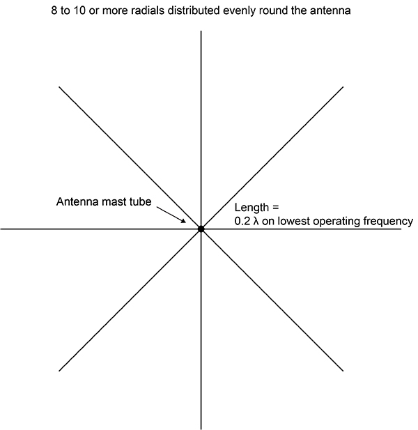
Therefore a radial system must be established with min. 4, but preferably 8 - 10 or more medium gauge copper wires with a length of ideally 0.2 wavelength at the lowest operating frequency, which fans out circular round the antenna.
The radials shall be placed on the surface of the ground, or buried just below the surface, in depth not more than an inch or so.
The radials are connected to an angled metal radial plate, which is clamped to the mast tube just above the ground surface.
ATU
The ATU shall be mounted on the mast tube with the antenna terminal upwards, just below the bottom end of the antenna whip.
The HF 5000 antenna feeder connection and the ATU antenna terminal are connected as direct as possible with a short open feeder wire, which in fact is a single piece of medium-gauge copper wire, self-supported or supported by some porcelain insulators. As high voltage can occur on the feeder wire, it must be mounted with a distance of min. 30 mm to the mast tube or other metal objects.
The ATU ground terminal is connected to the metal radial plate by heavy gauge wire or a metal strap. Generally, for details in the installation procedure, please refer to the ATU instruction manual, where installation examples often are described. This installation is valid for both coastal areas and built-up areas.
Vessel installations
The HF 5000 is only suitable for use on metal vessels.
In vessel installations, the vertical HF 5000 antenna must be mounted on a short suitable mast tube, which is connected to the vessel’s ground. The ATU shall be mounted either on the mast just below the bottom end of the antenna whip or somewhere on the vessel deck as close as possible to the antenna mast. The HF 5000 antenna feeder connection and the ATU antenna terminal are connected with a short open feeder wire.
The ATU ground terminal shall be connected to the vessel’s ground by a short heavy gauge wire or a metal strap.Generally, for details in the installation procedure, please refer to the ATU instruction manual, where installation examples often are described.
Typical land Installation

Suitable RF Ground System (top view)
Related products

Brackets and Mounts
Amphenol Procom design a wide and varied range of Wall Brackets and Antenna Mounting Poles. Robust professional install and longevity. See our collection here.

Corrugated Cables
Amphenol Procom offers several Corrugated Cables like Super Flexible- and Cobber Cables. All are of the highest quality on the market. See our collection.

Mobile Antenna Components
Amphenol Procom offer a wide range of Mobile Antenna Components, which incl. Connectors, Reinstallation Kits, Miniature Junction Box etc. Read more.
