- This active antenna has been designed for use on the UHF band e.g. TETRA, CDMA, ICE, and GPS.
- The antenna consists of a high-performance glass fibre- encapsulated antenna element and an active GPS antenna. The latter is built into the bottom part of the antenna together with a diplex filter. Only one down lead cable is therefore necessary.
- The antenna element is a ½ λ antenna for the UHF band frequency range within 380 - 467 MHz.
- The GPS antenna has a full hemispherical coverage and a built-in high-gain, low-noise amplifier.
- The necessary supply voltage (5 V DC) for the amplifier is delivered through the down lead coaxial cable. Up to 30 m of
RG 214/U coaxial cable can be used between the antenna and
the receiver/transceiver. - By careful choice of materials, the MA 70/GPS 4/... is designed to withstand the roughest of climate conditions, ensuring many years of trouble-free service.
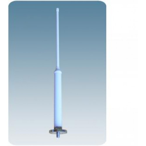
GPS AntennasMA 70/GPS 4/...
Dual Band Antenna for the UHF band e.g. TETRA, CDMA, ICE, and GPS.
Description
Specifications
| Electrical | ||
|---|---|---|
|
||
|
||
|
||
|
||
|
||
|
||
|
||
|
||
| Mechanical | ||
|---|---|---|
|
||
|
||
|
||
|
||
|
||
|
||
|
||
|
||
| GPS Antenna | ||
|---|---|---|
|
||
|
||
|
||
|
||
|
||
|
||
|
||
|
||
|
||
|
||
|
||
|
||
| Environmental | ||
|---|---|---|
|
||
Ordering Designations
| Model | Product No. | Description | Frequency | |
|---|---|---|---|---|
| MA 70/GPS 4/TETRA-l | 110000200 | 380 - 400 MHz | ||
| MA 70/GPS 4/TETRA-h | 110000201 | 410 - 430 MHz | ||
| MA 70/GPS 4/CDMA | 110000202 | 453 - 467 MHz | ||
| MA 70/GPS 4/ice.net | 110000223 | 453 - 467 MHz | ||
| MA 70/GPS 4/NET 1 | 110000224 | 453 - 467 MHz | ||
| Accessories | ||||
| DM Mounting Kit | 112000001 | |||
| SM-MAS | 110000196 | |||
| DIPX 1000/1550-DC-H | 200000749 | |||
| PRO-DIPX 1000/1550-DC-H | 200000799 | |||
| PRO-DIPX 1000/1550-DC-L XS | 200001622 | DC Pass: Low port | ||
| PRO-DIPX 1000/1550-DC-H XS | 200001998 | DC Pass: High port | ||
| PRO-DIPX 1000/1550-DC-LH XS | 200001999 | DC Pass: Low and high port | ||
| PRO-DIPX 1000/1550-NO-DC XS | 200002000 | No DC pass | ||
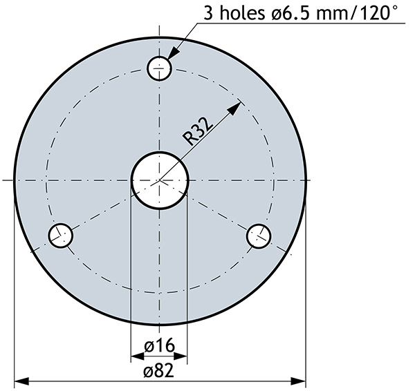
Mounting Details

Standard Mounting Kit included.

DM Mounting Kit for Deck Mount to be ordered separately.

SM-MAS Mounting Kit for Side Mount and Mast Mount to be ordered separately.
Mounting on flat surfaces
Diagram
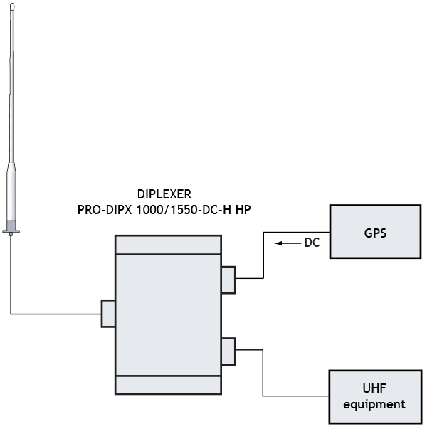
Alternatively, filter type DIPLEXER DIPX 1000/1550 N-DC-H can be used. Either filter to be ordered separately.
Typical Radiation Pattern for the UHF Band
Typical Radiation Pattern (E-Plane)

Typical Radiation Pattern (H-Plane)

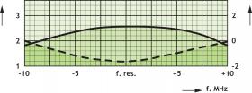
Typical Gain and VSWR curves
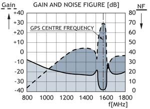
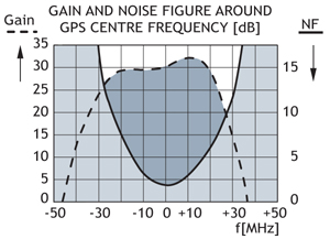
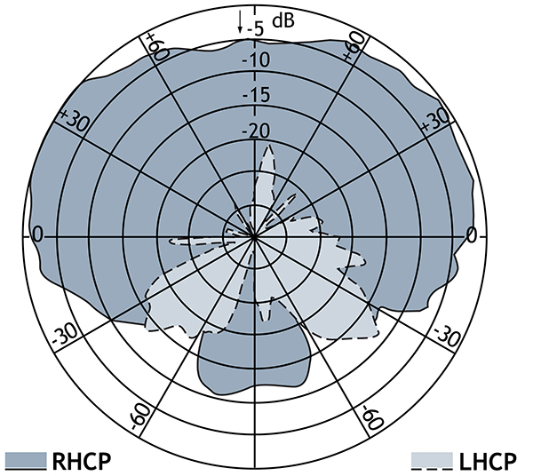
Typical Response curves and Radiation pattern for The GPS-part (1575 MHz)
Vertical Radiation Pattern
Related products

Brackets and Mounts
Amphenol Procom design a wide and varied range of Wall Brackets and Antenna Mounting Poles. Robust professional install and longevity. See our collection here.

Cable Connectors
Amphenol Procom offer quality Cable Components like Grounding Kits, Coaxial Loads, Attenuators, Arrestors, DC-blocks and SWR Analyzers. See our products here.

Corrugated Cables
Amphenol Procom offers several Corrugated Cables like Super Flexible- and Cobber Cables. All are of the highest quality on the market. See our collection.

Compact Combiners
View all Amphenol Procom hybrid Tx/Rx Compact combiners for VHF & UHF. To be used e.g. in mobile TETRA/PMR/LMR control stations. Learn more.

Base Station Antenna Components
Amphenol Procom offer a wide collection of quality Components for base station Antennas. Safety wire- and Grounding Kits, PMC’s and much more. Read more.

Braided Cables
Amphenol Procom a wide collection of Braided Cables which includes different RG Coaxial Cable models with low loss or ultra low loss. View our products here.

Low Noise Amplifiers
Our LNAs are small and medium sized. Low Noise Amplifiers by Amphenol Procom used for HF, VHF and UHF radio systems from 0.1-1600 MHz. Learn more here.

GPS Combination Antennas
Amphenol Procom have a huge assortment of GPS Antennas. Beneficial products for navigation/location applications. Read more here.